Unlock the Magic of Low Pass Filters The Definitive Guide to Circuit Diagram This article explores the analysis and design of passive low-pass filters. These circuits play an important role in a wide variety of systems and applications. The RC Low-Pass Filter We can attempt to create a second-order RC low-pass filter by designing a first-order filter according to the desired cutoff frequency and then connecting two
Active Low-Pass Filter Design Jim Karki AAP Precision Analog ABSTRACT This report focuses on active low-pass filter design using operational amplifiers. Low-pass filters are commonly used to implement anti-aliasing filters in data acquisition systems. Design of second-order filters is the main topic of consideration.
PDF Active Low Circuit Diagram
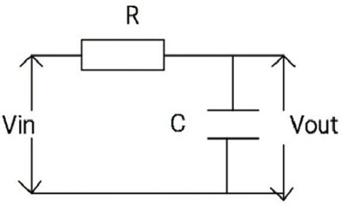
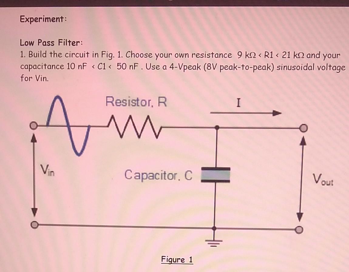
A low-pass filter (LPF) is designed to pass all frequencies below the cut-off frequency and reject all frequencies above the cut-off frequency. It is simply an RC series circuit across the input, with the output taken across the capacitor. At the cut-off frequency, the capacitive reactance of capacitor C is equal to the resistance of resistor R, causing the output voltage to be 0.707 times the
Whether you're designing an entire sound system complete with a bass boost, or just want to remove high-frequency noise, the low-pass filter calculator can help you create the perfect low-pass filter circuit for your needs. Read on to learn: What a low-pass filter is; The difference between passive and active low-pass filters; and

Passive RC Filter Tutorial Circuit Diagram
The following images depict the standard opamp based low pass filter circuits. The first one needs to be powered by a dual supply, and the second one works using a single supply voltage. Designing a Customized Low Pass Filter Circuit
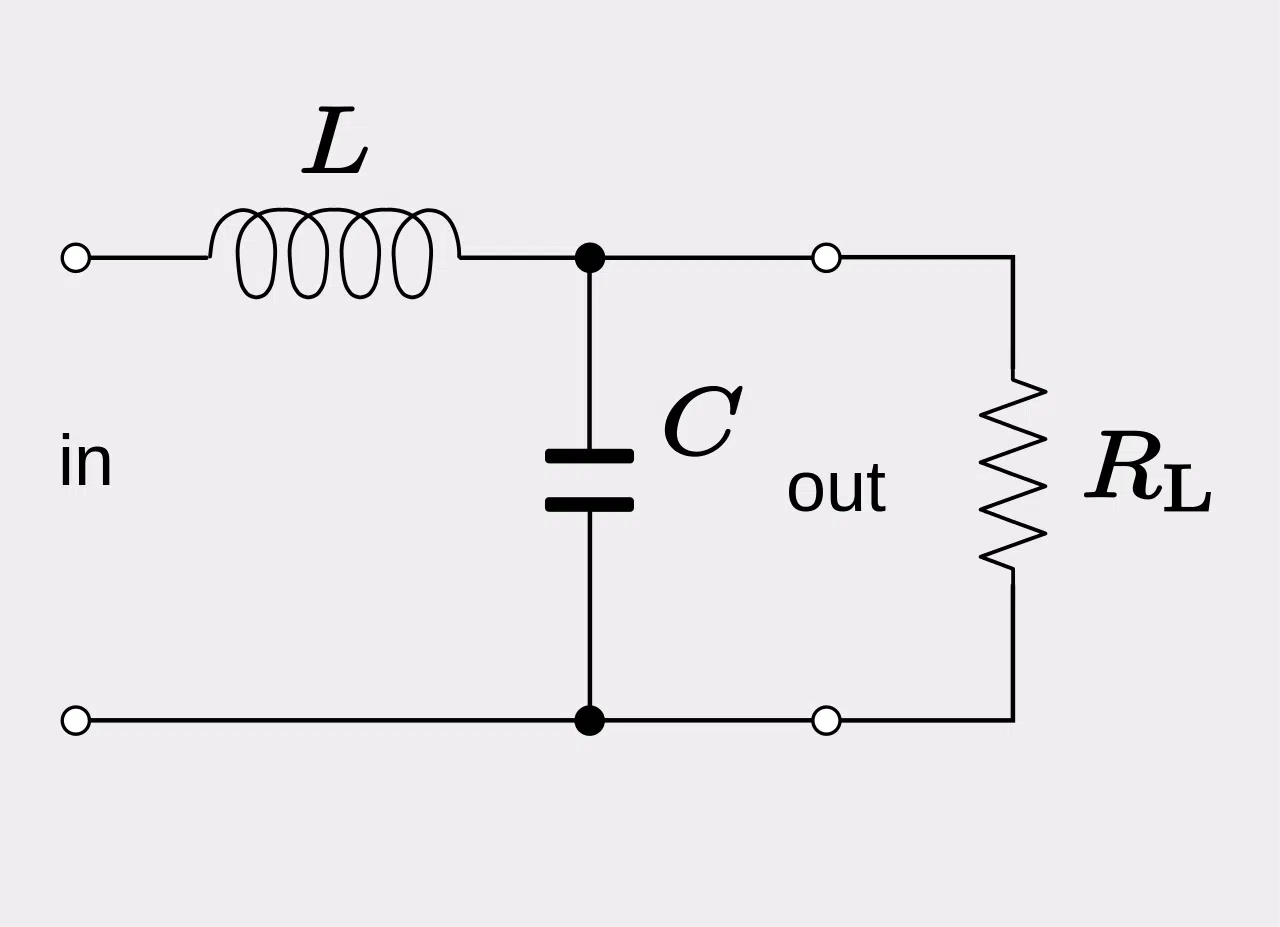
The formula and schematic for the LC low pass filter: Let's analyze a low pass filter with a practical example : Q. Design a low pass filter having cutoff frequency 'fc' = 75MHz and Vin = 5 volts using RC filter? Solution: given -> f = 75Mhz. R = 100 Ω(assumed)——-